| ������|�й��������̨|��վ��ͼ |
| �ͷ���Ϊ��ҳ |

| �ײ� |
|
|
| �ز� |
|
|
����
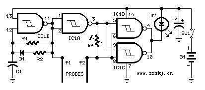 Parts:R1___________470K1/4W Resistor
R2_____________3K3 1/4W Resistor
R3___________100K 1/2W Trimmer Cermet��
C1_____________1nF 63V Polyester Capacitor
C2____________47��F 25V Electrolytic Capacitor��
D1__________1N4148 75V 150mA Diode
D2_____________5mm. Red LED��
IC1___________4093 Quad 2 input Schmitt NAND Gate IC��
P1,P2_______Probes (See text)��
SW1___________SPST Slider Switch��
B1______________3V Battery (2 AA 1.5V Cells in series)��
����Device purpose:
����This circuit is intended to signal when a plant is needing water. A LED illuminates at maximum brightness when the ground in the flower-pot is too dry: it dims gradually as the water��s content in the pot grows, turning off when the optimum moisture��s level is reached. This condition is obtained trimming R3.
����Circuit operation:
����IC1D forms a square wave oscillator with approx. 10/90 mark-space ratio. It feeds the output probe P1 and its signal, inverted by IC1A is compared with that picked-up by P2 in the NAND gates IC1B & IC1C in parallel, driving the LED. When a low resistance exists between the probes, due to an high water��s content in the flower-pot, the LED is off, turning gradually on as the resistance between the probes increases.
����Notes:
A square wave is used to avoid probes�� oxidization. Probes can be long nails, carbon rods obtained from disassembled exhausted 1.5V batteries, or even a couple of screwdrivers. The probes must be driven in the pot��s ground a few inches apart. Due to 3V supply, the LED needs not a limiting resistor. Power consumption: LED off = 50��A; LED full on = 1mA. To switch-off the circuit, you can short the probes. In this case SW1 can be omitted. Using an high-efficiency LED, brightness variations are better emphasized. In this case a limiting resistor could be necessary.�ȴʣ�
����㲥������̨ �й��������̨ ��Ȩ����
Υ���Ͳ�����Ϣ�ٱ� ��ICP֤060535�� �����ġ�2014��0383-083��
���ϴ���������Ŀ����֤�� 0102004 �³���֤��������098�� �й�������������Ŀ�������ɹ�Լ